
Glasfiber transmission uses light pulses to transmit information down fiber lines instead of using electronic pulses to transmit information down copper lines. The glasfiber transmitter converts an electrical signal into a corresponding optical signal. The source of the optical signal can be either a light emitting diode (LED), or an injection laser diode (ILD). The glasfiber receiver converts the optical signal back into a 'copy' of the original electrical signal.
The most popular wavelengths of operation for optical transmitters are 850, 1310, or 1550 nanometers. These wavelengths are near infrared. In a fiber optic system, these devices are mounted in a package that enables an optical fiber to be placed in very close proximity to the light emitting region in order to couple as much light as possible into the fiber. The glasfiber receiver converts the optical signal back into a 'copy' of the original electrical signal. There are two basic groups of fiber optics: Singlemode and Multimode.
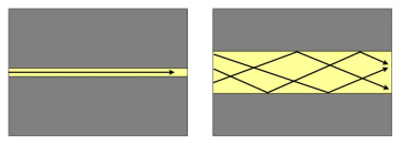
Singlemode cable is a single stand of glass fiber with a diameter of 8.3 to 10 microns that carries one mode of transmission. Because of the relatively narrow diameter only one mode will propagate through the cable. This 'cleaner' transmission in the singlemode cable compared to a multimode cable enables up to 50 times more signal transmission distance. It requires a light source with a very narrow spectral spectrum.
Usually used wavelength for singlemode cables are for single transmission 1310 and 1550nm and for multiplexed transmission 18 wavelengths between 1270 and 1610nm.
Multimode cable has a glass fiber diameter of 50 or 62,5µm. Light waves are dispersed into numerous paths, or modes, as they travel through the cable's core and cause signal distortion. Because of these distortions the cable length is more limited than with singlemode fiber. Usually used wavelength for multimode cables are 850 and 1310nm.
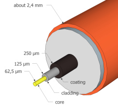
There are basically three parts of a fiber optics cable: the Core, the thin glass center of the fiber where the light travels, the Cladding, the outer optical material surrounding the core that reflects the light back into the core and the Buffer Coating, the plastic coating that protects the fiber from damage and moisture.
Materials:
- Ultra-Pure Glass
- Plastic Clad Silica (PCS), glass core with plastic cladding
- Plastic Fiber Optic, plastic core and plastic cladding
|
|
| glasfiber assembly | light path in singlemode fiber (left) and multimode fiber (right) |
 |
| glasfiber wavelengths 850nm, 1310nm, 1550nm |
| Dimensions (here: patch cables) | ||
 |
 |
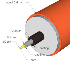 |
| singlemode 9µm (OS1, OS2) | multimode 62.5µm (OM1) | multimode 50µm (OM2, OM3, OM4) |
Generally two core sizes are used: 62,5 µm and 50 µm. Both cables have a cladding diameter of 125 µm. The usual labelling is: 50/125 and 62.5/125. 50 µm multimode fibers were first deployed in the 1970s, 62.5 µm fiber was introduced in 1985. Today, especially in Europe, only 50 µm cable is used. Multimode fibers are categorized by the 'Optical Mode' or 'Optical Multimode' (OM), defined by ISO/IEC 11801. Available are the types OM1, OM2, OM3, OM4. The latest version, OM4, was defined 2009 by TIA-492-AAAD.
OM1: bandwidth 200MHz-km at 850nm wavelength, 500MHz-km at 1300nm wavelength, max. attenuation 3,5dB/km at 850nm and 1,5dB/km at 1300nm, OM1 is typically a 62,5/125 µm fiber
OM2: bandwidth 500MHz-km at 850nm wavelength, 500MHz-km at 1300nm wavelength, max. attenuation 3,5dB/km at 850nm and 1,5dB/km at 1300nm, OM2 is typically a 50/125 µm fiber
OM3: bandwidth 2000MHz-km (EMB) and 1500MHz-km (OFL) at 850nm wavelength, 500MHz-km (OFL) at 1300nm wavelength, max. attenuation 3,5dB/km at 850nm and 1,5dB/km at 1300nm, OM3 is a 50/125 µm fiber
OM4: bandwidth 4700MHz-km (EMB) and 3500MHz-km (OFL) at 850nm wavelength, 500MHz-km (OFL) at 1300nm wavelength, max. attenuation 3,5dB/km at 850nm and 1,5dB/km at 1300nm, OM4 is a 50/125 µm fiber
EMB: effective modal bandwidth
OFL: over-filled launch
For 10G Ethernet an OM3 cable works for a maximum distance of 300m, an OM4 for a maximum distance of 550m. For future 40G Ethernet with OM3 only a maximum distance of 100m and with OM4 a maximum distance of 125m is possible.
Singlemode cables are categorized in OS1 and OS2 (Optical Singlemode 1 or 2 /ISO/IEC):
OS1: maximum attenuation 1dB/km at 1300nm to 1550nm
OS2: maximum attenuation 0,4dB/km at 1300nm to 1550nm
Because of the structure of singlemode cables more information can be transmitted at the same time. But the smaller core diameter makes coupling light into the core more difficult.
high definition video is always transported via singlemode glasfiber cables.
Because of the single mode transmission the theoretical bandwidth is nearly infinity but the practical bandwidth is restricted to about 100GHz. The transmission within singlemode cable is also restricted because of "chromatic dispersion". Different wavelengths arrive at the receiver at slightly different time intervals. This has an measurable effect only at very long distances.
The signal transmission at 1550nm has a narrower spectral response than the transmission at 1310nm and therefor enable longer transmitting distances. Transmitters at 1550nm are generally more expensive than transmitters at 1310nm.
To improve the transmission quality of multimode fiber optic cables, graded index cables were developed. The optical characteristics of the core material are altered by modifying the refractive index of the material. The refractive index of the glass fiber core decreases with increasing radial distance from the fiber axis. Usually the refractive index changes nearly parabolic from the center to the most outer layers of the core material. Because of this parabolic profile a continual refocusing of the rays in the core is accomplished.
With a changing refractive index from the inside to the outside of the core material light travels more slowly at the center and faster at the outer layers. Light that is bouncing around in modes near the outside of the core travels a longer distance but faster and arrives about at the same tome as the light travelling straight at the center of the core. Graded index fiber typically transmits about 600 to 1000 modes.
The standards OM2, OM3 and OM4 for multimode fibers imply the graded index specification!
 |
| graded index fiber |
There are two basic cable design types: loose-tube cable and tight-buffer cable. Loose-tube cables have multiple fibers per buffer and can be gel-filled, tight buffer cables have only one fiber per buffer and are not gel-filled.
1. Loose-Tube Cable / Universal Cable
With a modular design with typically 12 fibers per protecting buffer the loose-tube cable can have more than 200 individual fibers. The fibers are contained in small, rigid tubes, generally flooded with gel, stranded together, again flooded with gel. The modular design with separate buffers makes an easy drop-off of groups of fibers possible. All individual fibers are color-coded by EIA598-A or German code DIN VDE 0888.
The plastic buffer tubes are also color-coded. The inner space can be gel-filled or air-filled. The gel-filled version is better but more expensive. The individual fibers are free to move inside the buffer to release installation stress (bending) and environmental loading. Buffer tubes are stranded around a dielectric or steel central member, which serves as an anti-buckling element.
Typically the cable core uses aramid yarn and the outer jacket is extruded over the core. For strong armoring a corrugated steel tape can be formed around a single jacketed cable with additional jacket extruded over the armor.
The individual stripped fiber ends of a loose-tube cable are spliced to short pigtail cables that are connected typically to a 19" front panel.
2. Tight-Buffered / Breakout Cable
With tight-buffered design the buffering material is in direct contact with the fiber itself. This design is used for "Breakout Cables" there the fiber optic connector is fitted directly to the fiber without the use of a splice box. The tight-buffered cable ensures best fiber protection with maximum moisture and mechanical protection. This cable type enables easy handling, tight bend radius and easier pulling. The cable has no messy gel. Each individual fiber can be terminated directly with the proper fiber connector. All patch cables and pigtail cables for splicing use this design.
 | 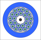 |
| loose-tube cable with 48 fibers with four buffer tubes, one filler tube and the dielectric strength member | tight-buffered / breakout cable with 24 fibers |
| Care should be taken bending glasfiber cables. The minimum bend radius should always be specified. A typical bend radius is 10 times the cable’s outside diameter. Bending a glasfiber cable too much may injure the inner core by creating micro cracks on the delicate glass fibres or cause the optical signal to refract. Even without injuring the material over bending always causes an increase in signal attenuation. |  |
| Position | Color Code EIA598-A | Color Code DIN VDE 0888 | Color Code IEC 60794-2 | ||||||
| in Tube | Individual Fiber Color | Individual Fiber Color | Individual Fiber Color | ||||||
| 1 | Blue | Red | Blue | ||||||
| 2 | Orange | Green | Yellow | ||||||
| 3 | Green | Blue | Red | ||||||
| 4 | Brown | Yellow | White | ||||||
| 5 | Slate | White | Green | ||||||
| 6 | White | Grey | Violet | ||||||
| 7 | Red | Brown | Orange | ||||||
| 8 | Black | Violet | Slate | ||||||
| 9 | Yellow | Aqua | Aqua | ||||||
| 10 | Violet | Black | Black | ||||||
| 11 | Rose | Orange | Brown | ||||||
| 12 | Aqua | Rose | Rose | ||||||
| 13 | Blue, Black Tracer | Red, Black Tracer | |||||||
| 14 | Orange, Black Tracer | Green, Black Tracer | |||||||
| 15 | Green, Black Tracer | Blue, Black Tracer | |||||||
| 16 | Brown, Black Tracer | Yellow, Black Tracer | |||||||
| 17 | Slate, Black Tracer | White, Black Tracer | |||||||
| 18 | White, Black Tracer | Grey, Black Tracer | |||||||
| 19 | Red, Black Tracer | Brown, Black Tracer | |||||||
| 20 | Black, Yellow Tracer | Violet, Black Tracer | |||||||
| 21 | Yellow, Black Tracer | Aqua, Black Tracer | Buffer 1: Red | ||||||
| 22 | Violet, Black Tracer | Transparent | Buffer 2: Green | ||||||
| 23 | Rose, Black Tracer | Orange, Black Tracer | Buffer 3: Transparent | ||||||
| 24 | Aqua, Black Tracer | Rose, Black Tracer | Buffer 4: Transparent | ||||||
Loopbacks are a common way to test installed optical fiber cables and connections. The test is accomplished by looping back the TX (transmit) pairs to the RX (receive) pairs. A complete optical link is created to allow the optical performance test and measurement. For instance for the multi-fiber MPO interconnection special loopback connectors are available that mate the individual fibers within the MPO connector.
There are four basic ranges of used wavelengths. The Wavelengths between 850nm and 1550nm are infrared and invisible, the (mostly consumer) wavelength of 660nm is in the visible range. The higher the wavelength is the lower is the loss.
| Wavelength | Loss | |
| first window | 850nm | 3dB/km |
| second window | 1310nm | 0.5dB/km |
| third window | 1550nm | 0.2dB/km |
| short distance transmission | 660nm |
Signal transmission can be done in both directions at the same time with different wavelengths. A bi-directional transmission could be for instance a transmission at 1310nm in one direction and at 1550nm at the opposite direction. At each side a transmitter and a receiver is positioned, the light signal is diverted by filters or prisms.
Plastic optic fibers are fiber optic cables with a plastic core carrying the information in the form of light. Plastic optic cables work only on very short limited lengths. Toslink is the most usual plastic optic fiber.
These cables have a plastic core with a diameter of 960µm, 100 times the diameter of the singlemode glass core and about 20 times the diameter of the multimode glass core.
Tactical fiber cables are extra strongly armored with fiberglass yarn or steel tape. They are designed and approved to withstand high physical stress. They are available with all regular core quantities. Designed extremely strong and rugged, lightweight, with exceptional mechanical protection for the optical fiber they can survive on the military tactical field. They can be used outdoors on all terrain, including severe environment, temperature range -40°C to +60°C. They are used with rugged multi-way military tactical field connectors.
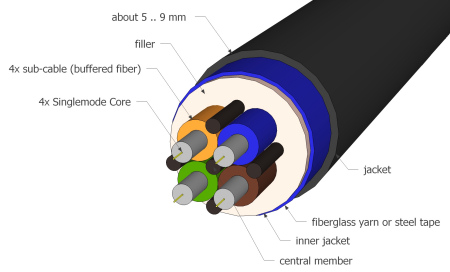 |
| tactical fiber cable (4x singlemode) |