The inductive loop system is one version of the Assistive Listening Systems (ALS) in order to use the direct-proximity of the user's ear in order to amplify a selected sound source to people with some form of hearing loss. These systems reinforce the audio signal and help to overcome background noises.
Common other systems are frequency modulated (FM) and infrared (IR) systems.
The inductive loop system consists of the audio signal source, the loop amplifier, the wire loop and the inductive receivers. The induction loop system enables an audio signal to be transmitted to a listener via a magnetic field, generated by the inductive loop system. The magnetic field may be picked up by different devices like standard type hearing aids or dedicated loop receivers.
How it works:
A current flowing in a wire creates a magnetic field around that wire. This magnetic field is received by a small coil in the listening device and will be amplified by the electronics in the receiver.
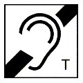
Most hearing aid receivers have a switch to choose between the inbuilt microphone (marked 'M') and the magnetic receiver (marked 'T').
The loop amplifier must be properly matched to the load requirements of the inductive loop. The use of inappropriate amplifiers to drive the inductive loop results in poor performance.
The induction loop is built by one or several turns of insulated wire, installed in the floor of the listening area or around the listening area at a suitable height. Good results are often obtained by fitting the wire around the listening area at the skirting board. An isolated copper wire under the carpet can also provide a good result.
The covering magnetic field can be created with a single wire turn loop and an appropriately high powered amplifier. Using several loops in the same room increase the field strength but reduce the frequency response of the transmitted audio signal.
Nonetheless, in a certain on-site situation the mains wiring, fluorescent lighting or steel structures can cause problems to the signal transmission via the inductive loop system.
The electromagnetic field produced by a conventional loop system spreads somewhat beyond the region enclosed by the loop. This is problematic several different loops with different signals. In such cases, users may pick up signals from adjacent looped regions.
Frequency range:
Speech, in the short term where intelligibility is crucial, requires that the system must handle full power signals up to at least 1.6 kHz.
Usual amplifier details:
'metal loss corrector': permits correction of the system frequency response when losses occur due to metal constructions on site. Loss adjustment in dB per octave.
'loop current': several Ampere signal current
'output voltage': usually between 10 .. 50 Volts peak
'loop impedance, DC resistance': between 0.2 Ohms .. 2O Ohms
Loop wire:
Stranded copper cable with good insulation is the easiest to install and most robust in use. The certain type of wire is not too important.
For a usual amplifier a cable of 0.75 mm2 can make a loop with a total length of 10 to 100 meters, a cable of 2.5 mm2 a loop with a total length of 40 to 200 meters (depending on the power of the amplifier).
Too short wire will stress the amplifier too much (load). If the wire is too long, the full power cannot be transmitted at the critical maximum frequency of 1.6 kHz (the energy distribution in speech reaches a maximum at that frequency).
Standard (Europe): EN 60118-4